Fabric Expansion joints-----Installation Guide
- Pre-installation checks
Please check the following items before installing the expansion joint:
- Confirm expansion joint design
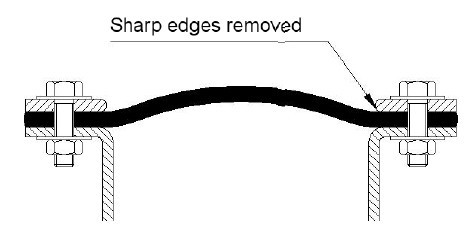
- Duct flanges are in a good condition and are fully and continuously welded and free of sharp edges, burrs etc.
- Dimensions and holes on Duct flanges and installation measurements are correct
- Dimensions on Duct flanges are correct and according to specification (Especially important are the breach opening, installed length and the bolting detail)
- Whatever design method is used, ensure that the fabric does not foul the adjacent metalwork under operating conditions.
- All metal edges in contact with Flexible materials must have sharp edges removed (to avoid cutting)
- Ensure the correct orientation of the expansion joint with regard to duct flow direction if the expansion joint is market accordingly match flow arrow direction on the expansion joint with duct
- Where fitted, internal flow sleeves must be in good order and in the correct orientation.
- The necessary amount of bolts, nuts, and washers are available.
For flanged expansion joints, please check in addition:
- Bolt heads do not damage the outer layers of the expansion joint during operation.
- In confined spaces or when large movements are likely, countersunk or carriage head bolts may be required
Please contact the supplier in any case where packing is damaged during transport or storage.
If one or more of the above items are found to be wrong when compared with specifications, please contact the manufacturer immediately.
Never install damaged components!
- Handling for installation
It is assumed that the expansion joint and its components are now at the point of installation and hence will be stored for a short period only just prior to installation. For short term storage, the following conditions should be observed:
- During short storage outside, the flexible element (and bolster, if included) must be covered with an appropriate weather-proof cover and should be protected against humidity and dampness from the ground
- An ideal temperature to install components to give optimum handling is around 20℃, Progressively below this temperature, materials become stiffer, making handling difficult, under these conditions, it is recommended that the expansion joint should be stored inside a warmer environment immediately prior to installation.
For any movement required at the point of installation:
- Unpacked expansions joints must be placed on a secure based (e.g: pallet) and must be protected temporarily during any site transportation.
- The attachment points for the lifting equipment must be on the base (pallet)
- Where appropriate, always use several persons for carrying
- Do not drag expansion joints or bolsters along the ground or across edges
To ensure correct installation, and thereby preserve the reliability and working life of the expansion joint, the following instructions must be observed:
- Ensure components are installed in the correct sequence.
- Erection of suitable scaffolding around the workplace is essential for efficient installation
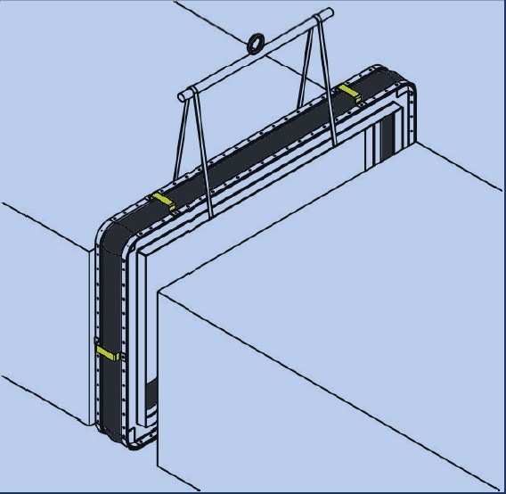
- Large and heavy expansion joints must be supported during installation and should be installed with appropriate lifting equipment.
- Fabric expansion joints must not be lifted by attaching the lifting device directly to the fabric, the fabric expansion joint should rest on a supporting base, to which lifting tackles can be attached.
- The holes in the expansion joint flange should never be used to lift the expansion joint
- At all times, protect the expansion joint from welding sparks and sharp objects, where appropriate.
- Never walk on, or place scaffolding on the expansion joint
- Fabric expansion joints which have been pre-assembled by the manufacturer must be lifted by the lifting points and not by their shipping straps(unless the manufacturer has combined the two specifically)
- Any protective cover and/or shipping straps must not be removed until installation is completed, but must be removed immediately prior to plant start up.
- Installation of bolster
If no bolster is included in the design, please ignore this section and go on to section 4.
A bolster can be installed in several different ways, depending upon the individual design and construction, and way have specific additional instructions supplied by the manufacturer. Specific note should be taken of:
- It is essential that the bolster must be kept dry during installation and until the flexible element provides a weather-proof cover (take care also that water does not come down inside the ducting)
- If the bolster has integral flanges, then in principle it should be wrapped around the ducting and secured temporarily with suitable clamps which support the unit adequately.
- Joining or splicing of the bolster should be carried out according to manufacturers instructions (please see section 4, Joining or splicing)
- The outer flexible element should be wrapped around the ducting on top of the
bolster and both items secured together.
- In the case of loose bolsters, these should be wrapped around the ducting (as mentioned above), in some instances, the use of clamps is not practicable and in these instances a suitable thread can be used to tie across the breach opening to support the bolster, this thread may be left in situ when the expansion joint is fitted (note, the thread may break when the expansion joint is moved, but this is not a problem.)
- Other fixation methods are available, for example pins and washers fitted to side wall for fixing u-shaped bolsters. These will be specified by the manufacturer.
|


